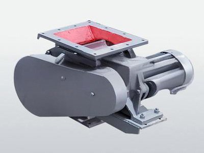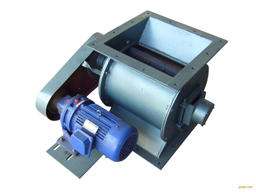
1.1. Overview
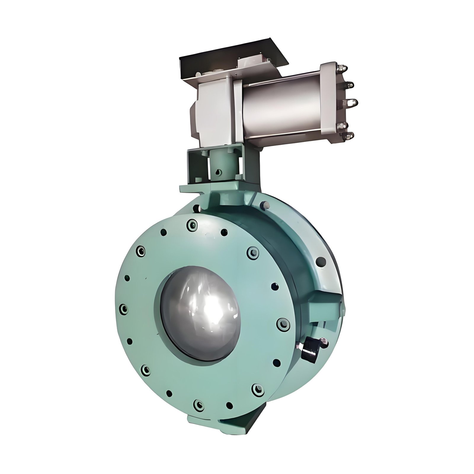
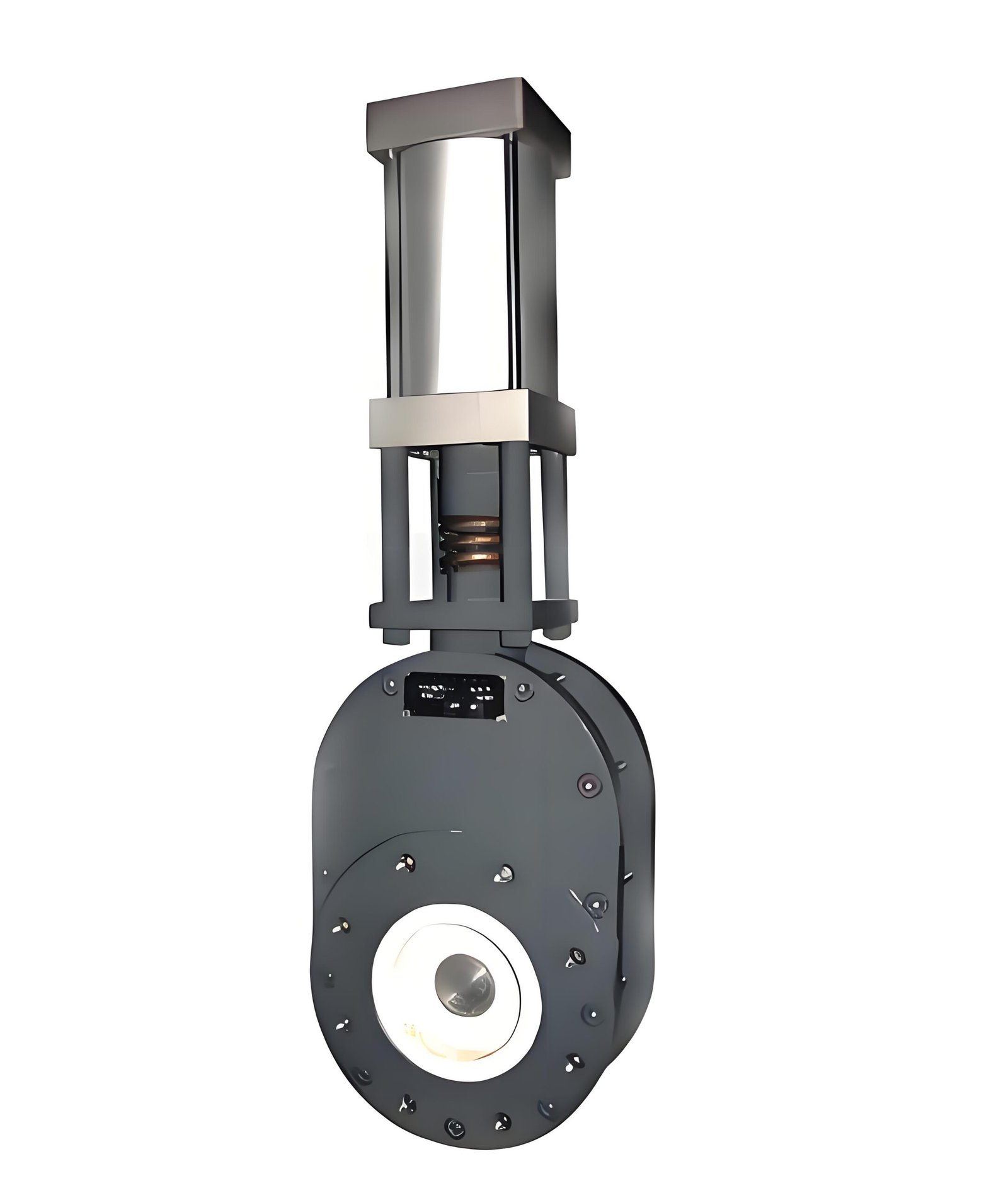
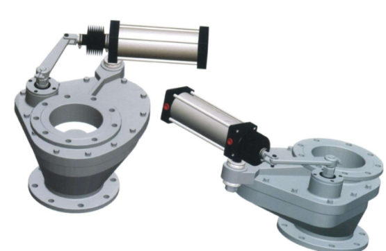
BDF series swing valve seal with carbide or toughened ceramic friction pair, strong wear resistance, good sealing. This series of valves has the advantages of small starting load, no ash accumulation and jam in valve chamber, good adaptability to working conditions and long service life.
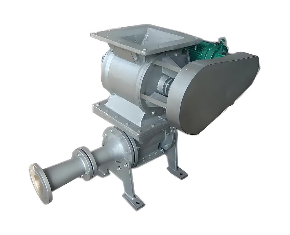
1.2. Working principle
The pneumatic actuator makes the valve plate swing through the rocker arm, rotating shaft and swinging arm. The spiral compression spring is loaded between the valve plate and the sealing surface. The spring force always makes the valve plate closely fit with the sealing ring surface, and allows the valve plate to move in the vertical direction, which helps to compensate the thermal expansion and contraction of the valve parts, and can overcome the influence of any change in back pressure on the seal. It also prevents granular media from entering between the sealing surfaces. The difference of friction between the valve plate seal face and the sealing ring in the tangential direction enables the valve plate to rotate during opening and closing, which leads to grinding and polishing between the sealing surfaces. All of these features make this swing valve with superior service life, providing a reliable guarantee for your system safety.
1.3. Main technical parameters
Nominal pressure: 1.0MPa
Medium temperature: ≤25 ℃
Strength test: 1.5MPa
Seal test: 1.1MPa
The working pressure of the cylinder is 0.4MPa-0.6MPa, clean, dry, oil-free compressed air on using .
1.4. Installation and use points
Before installation, check the pneumatic actuator of the valve and see if there are any defects such as damage and depression.
Check whether the length, nominal pressure and nominal diameter of the connecting flange structure meet the requirements.
Do not adjust the bolts and nuts that have been tightened before delivery. In addition, it should be noted that the center of the two pipes and the center of the valve diameter should be kept coaxial, the flange surface should be flat, and no large deviation is allowed to ensure the clamping and normal operation of the valve, and the force should be uniform and symmetrical when tightening the bolts.
After installation, pass the air source through the two air intakes of the pneumatic actuator, and confirm that the valve plate opens and closes normally.
If a control switch is installed, it should also be checked whether the switch is fixed firmly, whether the use parameters are consistent with the access power supply, and whether it is fully closed
Regular inspection of the operation, the occurrence of abnormal conditions should be timely and correct processing.
The valve has been adjusted and dynamic test before leaving the factory, and the gas path has been connected.
1.5. Common faults and troubleshooting methods
| Fault phenomenon | Cause analysis | Elimination method |
| Leakage of sealing surface | There is dirt between the valve plate and the sealing surface | Clear foreign body |
| Seal secondary damage | Repair or replace | |
| The cylinder cylinder is damaged | Check whether the cylinder is not round due to knocking or collision, and replace the cylinder if there is. | |
| Cylinder piston seal ring wear caused by serial cylinder | Replace the cylinder piston seal ring | |
| Valve leaks when closed | The sealing surface of the spool and valve plate is worn | Replace the spool and plate |
| The spool is not closed in place, and there are foreign bodies in the inner wall of the valve cavity | Clean the inner wall of the valve cavity | |
| The sealing ring at the shaft is worn | Reseal | |
| No return signal | The position of the signal cable is incorrect | Adjust to the optimum magnetic sensing zone |
| The signal switch line is incorrect or the signal line is damaged | Connect the signal switch line correctly or replace the signal line |
1.6. Installation dimensions and outline drawing
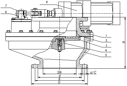
| Diameter DN | H | D | K | d | n-C |
| 50 | 245 | 165 | 125 | 99 | 4-ø18 |
| 65 | 260 | 185 | 145 | 118 | 4-ø18 |
| 80 | 260 | 200 | 160 | 132 | 8-ø18 |
| 100 | 280 | 220 | 180 | 156 | 8-ø18 |
| 150 | 310 | 285 | 240 | 210 | 8-ø22 |
| 200 | 310 | 340 | 295 | 265 | 8-ø22 |
| 225 | 310 | 370 | 325 | 295 | 8-ø22 |
| 250 | 330 | 395 | 350 | 320 | 12-ø22 |
| 300 | 330 | 445 | 400 | 368 | 12-ø22 |
| 200*350 | 310 | 340 | 295 | 265 | 8-ø22 |
| 520 | 470 | 8-ø26 | |||
| 200*350Y | 205 | 340 | 315 | 265 | 8-M12 |
| 520 | 470 | 8-ø22 | |||
| 300*450 | 330 | 445 | 400 | 370 | 12-ø22 |
| 690 | 630 | 12-ø26 |
1.7. main parts
| Serial number | Name | Material | Serial number | Name | Material |
| 1 | Upper valve seat | Ductile cast iron | 5 | Lower valve body | Nodular cast iron |
| 2 | Sealing ring | Ceramic or alloy | 6 | Swing arm | Nodular cast iron |
| 3 | Valve plate | Ceramic or alloy | 7 | Pivot | 45# steel |
| 4 | Swing arm | Ductile cast iron | 8 | Pneumatic actuator | Aluminum cylinder |